RF Coils#
With a stable magnet in place, attention shifts to the RF hardware — essential for both transmitting and receiving signals.
The process starts with hand-winding copper wire into a solenoid coil. This simple but precise step defines the sensitivity of the system.
Next, the transmit/receive (TR) switch is built to alternate between exciting the spins and detecting the returning signal.
Shielding is added to protect the switch from external noise and unwanted coupling.
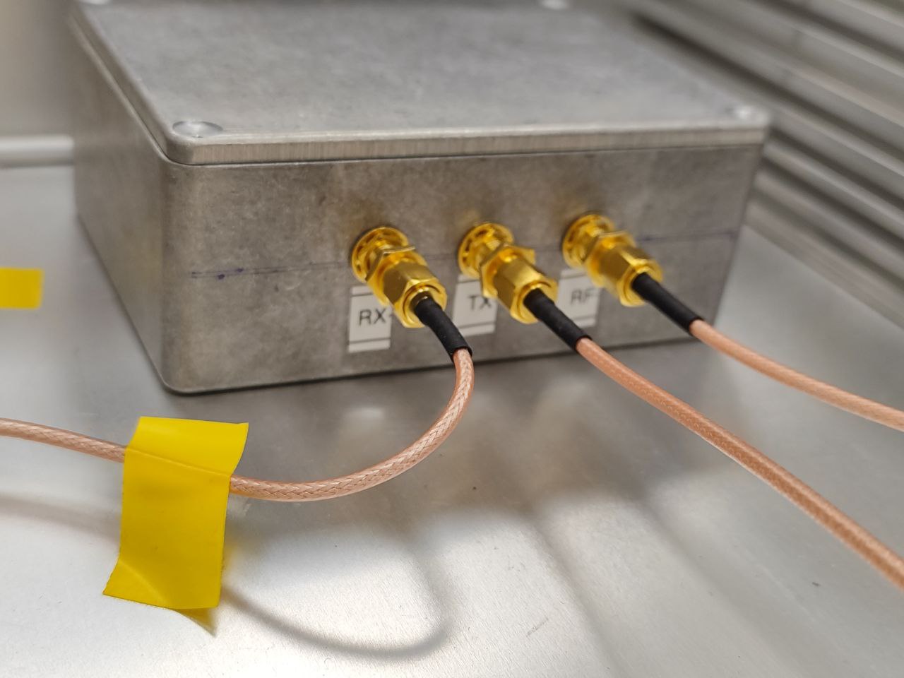
Shielding the TR switch.#
The electronics chain is then expanded with filters, amplifiers, and a regulated power supply, ensuring clean operation.
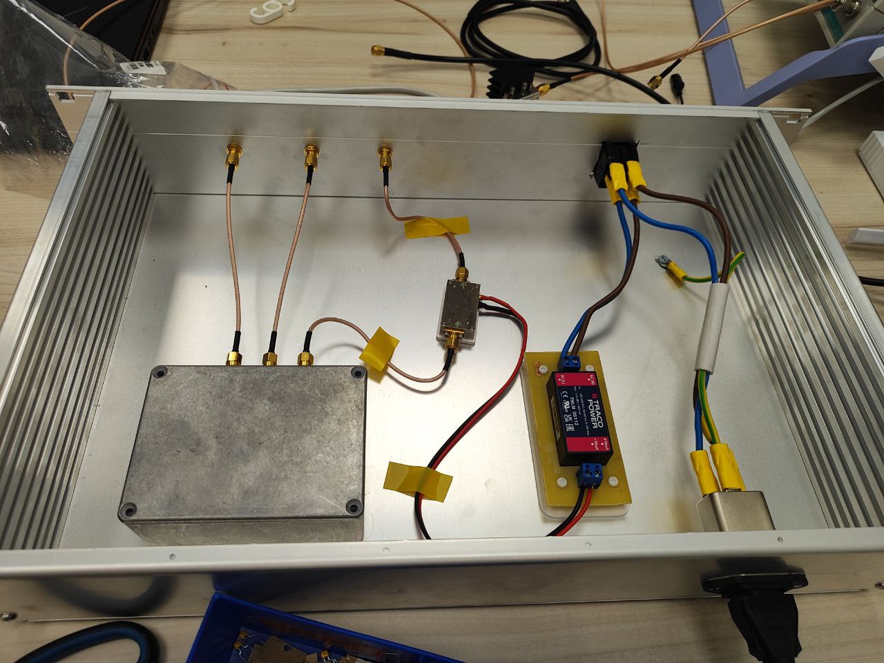
Adding noise filters, amplifiers, and power supply.#
Once complete, the RF assembly is installed into the scanner.
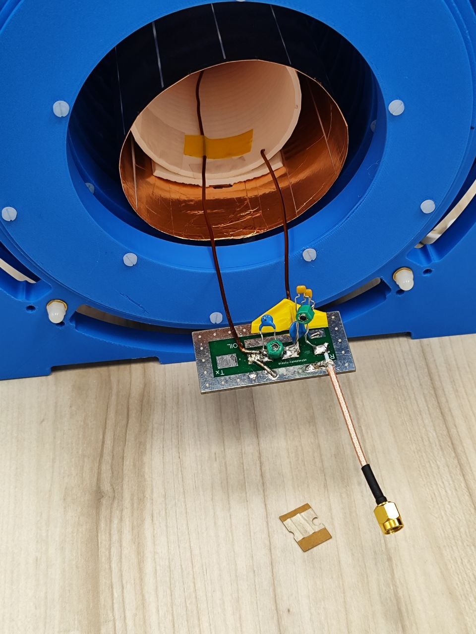
Placing the RF switch inside the scanner.#
With everything connected, the system is ready.
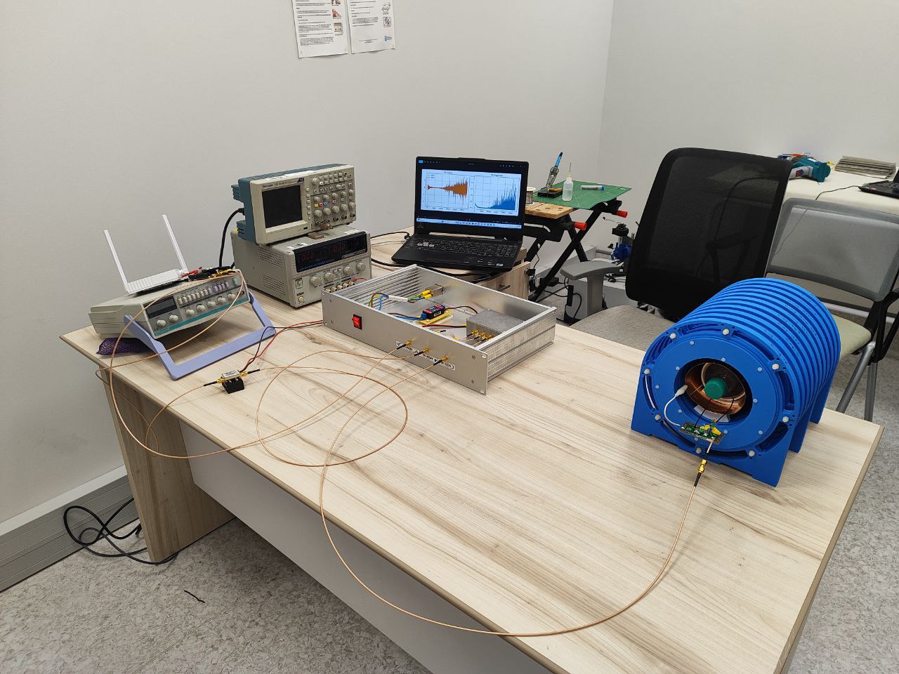
Whole setup#
The first Free Induction Decay (FID) signal marks the successful operation of the low-field setup.
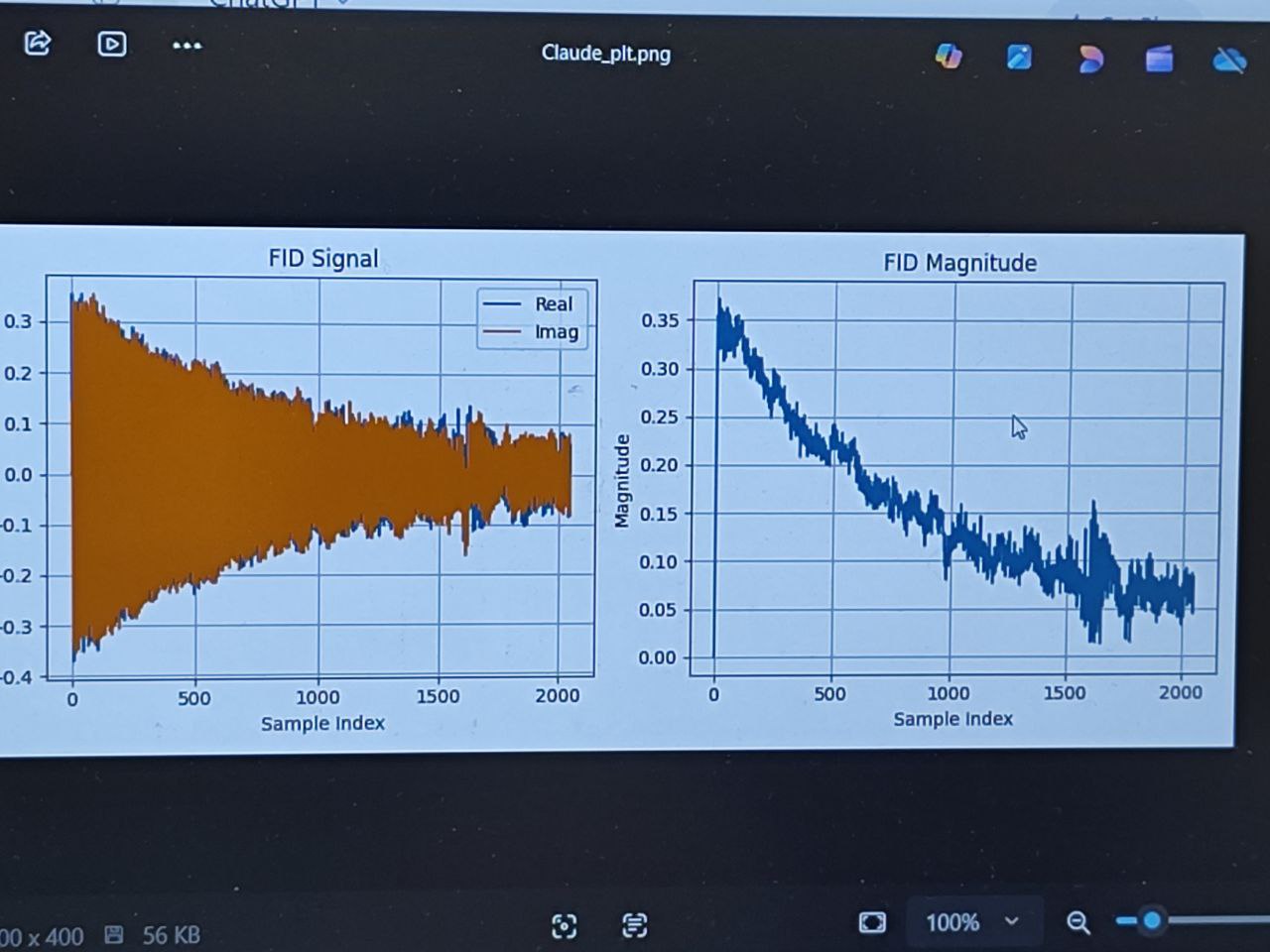
Capturing the first FID signal.#